
Network segmentation with VLANs to limit lateral movement
Network segmentation with VLANs to limit lateral movement
This project started as a personal lab I built to strengthen my networking and security skills.
I treated it as if I were a junior systems or network engineer asked to improve a small company’s security posture by redesigning their internal network.
The focus was simple: use VLANs and access control to make it much harder for an attacker to move around the network once they are inside.
1. Scenario and “Before” State
The fictional company is a small-to-medium enterprise (SME) with:
- Office users
- Internal servers
- IT administrators
- Guest Wi‑Fi for visitors
The original network looked like something I’ve seen in a lot of real small businesses:
- One flat network
- Single subnet:
192.168.1.0/24 - No separation between users, servers, management or guests
- No traffic restrictions
In practice this meant:
- Any compromised user workstation could talk directly to file servers, management interfaces and printers.
- Guest Wi‑Fi sat on the same network as everything else.
- Attackers who got one foothold could scan and move laterally with almost no friction.
Before – Flat Network
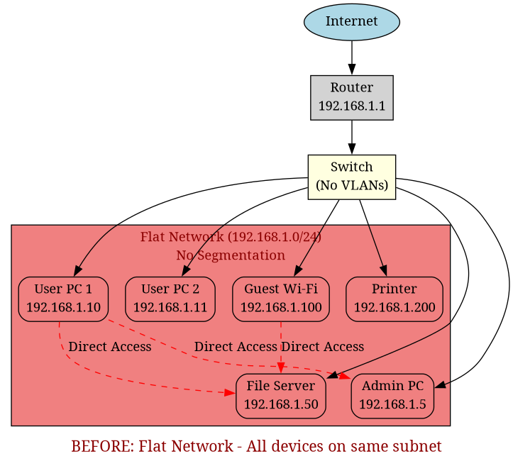
The diagram above shows the original flat network where all devices—users, servers, guests, and IT administration—exist on the same subnet (192.168.1.0/24) with no separation or access controls. This means any compromised device can directly communicate with any other device on the network.
2. Tools and Lab Environment
I built and tested the design in Cisco Packet Tracer using:
- Cisco 2960 switches
- A Cisco router (router‑on‑a‑stick model)
- PCs and servers acting as end devices
This setup let me fully configure VLANs, trunk links, subinterfaces, ACLs and routing, and then verify everything with pings, traceroutes and simulated “attacks”.
3. Target Design – Segmented Network
VLAN Design
I created five VLANs, each with a clear purpose:
VLAN 10 (Management): This VLAN handles switch and router management interfaces, along with IT administrator workstations. It's the most privileged segment, allowing full access to network infrastructure for maintenance and configuration.
VLAN 20 (Servers): This segment contains internal application servers and file servers. These are critical business systems that need protection from general user access whilst still being accessible for authorised services.
VLAN 30 (Users): Employee workstations connect to this VLAN. It's the largest segment in terms of device count, containing all standard office PCs and laptops used by staff for their daily work.
VLAN 40 (Guest): Guest Wi‑Fi access points and visitor devices connect here. This VLAN is completely isolated from internal resources, providing Internet access only to maintain security whilst accommodating visitors.
VLAN 50 (IoT): Printers and other smart or IoT devices are placed in this segment. These devices often have limited security capabilities, so isolating them prevents them from being used as attack vectors into more sensitive network areas.
I used logical VLAN IDs (10, 20, 30, 40, 50) rather than sequential numbering. This keeps the design tidy and leaves room for future expansion—I could add VLAN 15 for a specific department or VLAN 25 for additional servers without disrupting the logical grouping.
After – Segmented Design
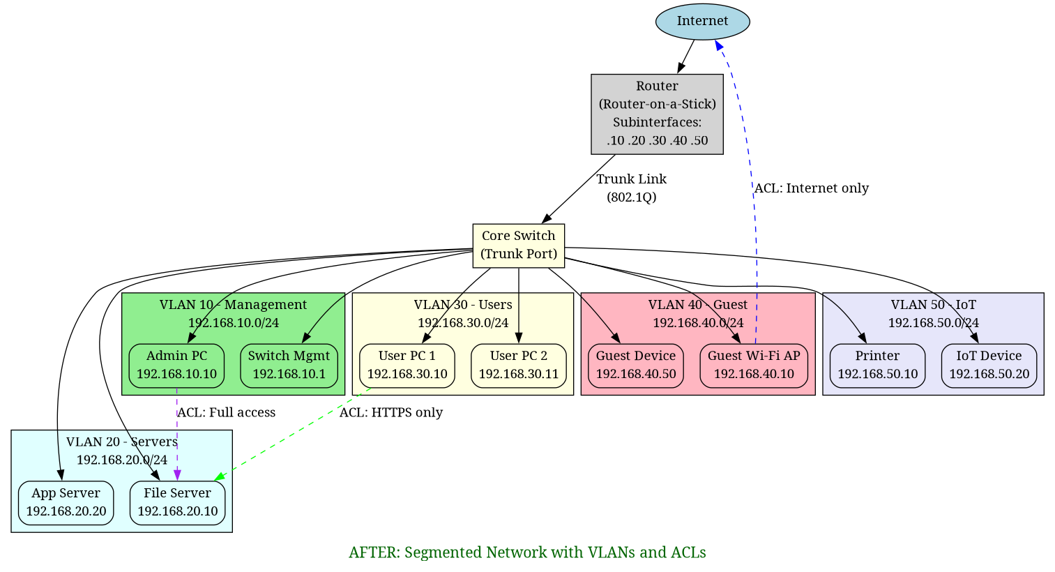
The diagram above illustrates the redesigned network with five distinct VLANs, each isolated and connected through a router-on-a-stick configuration. The router subinterfaces handle inter-VLAN routing, whilst ACLs control which VLANs can communicate with each other. This segmentation creates clear boundaries between different network functions and user groups.
All inter‑VLAN routing happens on the router using router‑on‑a‑stick with 802.1Q tagging on the trunk link.
4. Implementation Steps
4.1 Create VLANs on the Switch
On the core switch I created the VLANs and assigned access ports:
- Access ports for end devices (e.g. PCs, servers, APs, printers)
- Trunk port between the switch and router carrying all VLANs
Conceptually:
Switch ports
------------
Fa0/1  -> VLAN 30 (User PC)
Fa0/2  -> VLAN 30 (User PC)
Fa0/5  -> VLAN 20 (Server)
Fa0/10 -> VLAN 40 (Guest AP)
Fa0/15 -> VLAN 50 (Printer)
Gi0/1  -> Trunk to router (VLANs 10,20,30,40,50)
4.2 Configure Router-on-a-Stick
On the router I created subinterfaces for each VLAN, enabled 802.1Q tagging and assigned gateway IPs:
Gi0/0.10  -> 192.168.10.1/24  (Management)
Gi0/0.20  -> 192.168.20.1/24  (Servers)
Gi0/0.30  -> 192.168.30.1/24  (Users)
Gi0/0.40  -> 192.168.40.1/24  (Guest)
Gi0/0.50  -> 192.168.50.1/24  (IoT)
This allowed devices in each VLAN to reach their default gateway and, where permitted, talk to other VLANs or the Internet.
4.3 Implement Access Control (ACLs)
With routing in place, I added extended ACLs on the router to control which VLANs could talk to which:
- Users (VLAN 30) → Servers (VLAN 20): allow only specific service ports (e.g. HTTP/HTTPS)
- Guest (VLAN 40) → Internal VLANs (10,20,30,50): deny all; allow only Internet
- Management (VLAN 10): allow full access to all VLANs for administration
- IoT (VLAN 50) → others: restrict to only what is required (e.g. print server)
In plain English:
- Guests can browse the web, but cannot see anything on the internal network.
- Employee PCs can reach servers only on the ports they are meant to use.
- Only the management VLAN can administer network devices.
- Printers and IoT kit cannot start conversations with users or servers beyond what is strictly needed.
5. How Segmentation Limited Lateral Movement
Once the VLANs and ACLs were in place, the behaviour of the network changed dramatically.
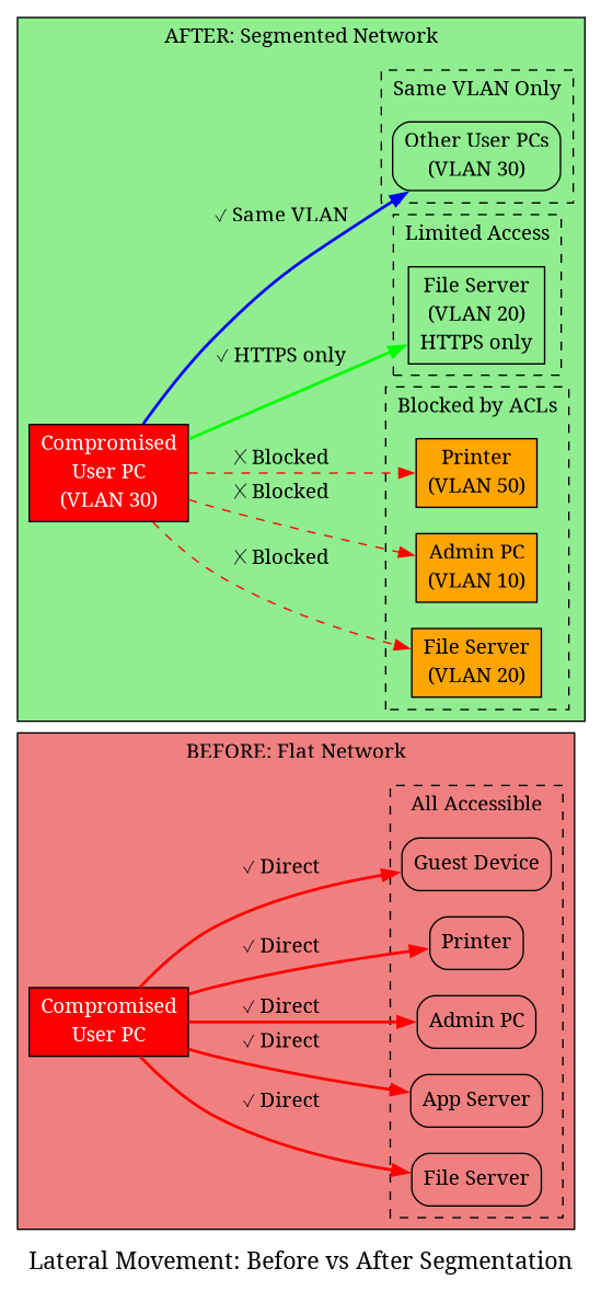
The diagram above visually demonstrates how network segmentation limits lateral movement. On the left (before), a compromised device can access everything. On the right (after), the same compromise is contained within the user's VLAN, with only limited, controlled access to servers.
Before
If an attacker compromised one user PC:
- They could scan the entire
192.168.1.0/24range. - They could discover file servers, admin interfaces and printers.
- They could attempt lateral movement to any device on the network.
After
Now, if an attacker compromises a PC in the Users VLAN (30):
- Their scans only show other devices in the Users VLAN.
- Attempts to reach servers on non‑approved ports are blocked at the router.
- They cannot talk directly to management interfaces or IoT devices.
If a device on the Guest VLAN (40) is compromised:
- It has Internet‑only access.
- Any attempt to reach internal subnets is blocked by the ACLs.
If an IoT device (VLAN 50) is taken over:
- It cannot start arbitrary connections to user machines or servers.
- It can only reach the specific services it needs (for example, a print server).
In short: compromise no longer equals full internal access.
6. Testing and Verification
To verify that the design actually worked, I simulated attacks and misuse from different VLANs:
6.1 Ping and Port Access Tests
-
From a Guest VLAN host, I tried to ping and connect to internal server IPs.
→ Pings and connection attempts failed, as expected. -
From a User VLAN host, I tried to access server ports that were not allowed in the ACLs.
→ Connections were blocked whilst allowed ports (e.g. HTTPS) still worked.
6.2 ACL Counter Checks
I checked ACL counters on the router to confirm:
- Deny rules were actually being hit when I tested blocked traffic.
- Permit rules were hit for legitimate traffic.
6.3 Routing Sanity Checks
I verified:
- Each VLAN could reach its default gateway.
- DNS and Internet access worked where expected.
- No “accidental” routes allowed unwanted cross‑VLAN traffic.
This testing step was where I really saw the design come to life.
7. Threats Mitigated
The new design directly reduced the impact of several realistic threats:
-
Malware spreading laterally
In the flat network, one infected PC could quickly spread malware across the entire subnet.
With VLANs, the blast radius is limited. -
Guest Wi‑Fi abuse
Guests can no longer accidentally (or intentionally) browse internal resources. -
Insider threats
Users cannot casually poke at servers or management interfaces outside their role. -
Compromised IoT devices
Printers or “smart” devices are isolated and cannot easily be used as a pivot into more sensitive areas.
8. Challenges and “Aha” Moments
This was not just a configuration exercise; I hit a few real learning points:
ACL Direction Confusion
Understanding inbound vs outbound ACL application on router subinterfaces took a bit of trial and error.
I learnt to think in terms of:
- “From where is the traffic coming?”
- “Where do I want to check and possibly drop it?”
Trunk Misconfigurations
At one point my VLANs simply “didn’t work”.
The cause: a trunk port that wasn’t properly allowing all the VLANs.
Fixing the trunk and allowed VLAN list made everything click into place.
The Big Aha
The key insight from this lab was:
Security is not about blocking everything. It’s about allowing only what is actually required.
VLANs and ACLs gave me a very concrete way to apply that principle.
9. Why This Matters for Fraud Prevention and Risk Management
This project is a good example of the kind of thinking a fraud analyst needs every day.
Risk Assessment and Solution Design
I started from a business problem:
"We handle sensitive data and we do not want one compromised device to bring down the whole network."
From there I:
- Designed a modular, scalable network architecture using VLANs to contain risk.
- Mapped business roles (users, guests, admins, IoT, servers) to risk-based controls.
- Implemented a solution that could realistically be deployed in a small company.
Stakeholder Communication
If I were explaining this to stakeholders, I would keep it simple:
"Right now, if one device is compromised, the attacker can move freely inside your network.
With segmentation, even if something goes wrong, the attacker is trapped in a small part of your network."
Then I can show:
- Before/after diagrams
- Which groups are isolated
- What traffic is still allowed and why
Business Benefits
From a business view, this brings:
- Reduced risk and impact from attacks
- Easier troubleshooting (issues are contained within one segment)
- Improved compliance posture (data is better isolated)
- More stable and predictable network behaviour
10. What I Learnt
This lab reinforced a few important lessons:
-
Network security starts with architecture.
If the design is wrong, no amount of patching will fully fix it. -
Segmentation is foundational, not optional.
Especially for organisations handling sensitive data. -
Documentation and diagrams matter.
Being able to clearly explain the “before” and “after” states is just as important as the configs.
Overall, this project took a very common real‑world problem—a flat, insecure network—and showed how thoughtful network segmentation with VLANs and ACLs can dramatically improve security without making the network unusable.
It's exactly the kind of practical, solution‑oriented work I want to do in fraud prevention and risk management.